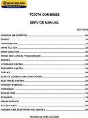
CONTENTS
This manual contains high quality images, diagrams, instructions to help you to operate, maintenance, diagnostic, and repair your truck. This document is printable, without restrictions, contains searchable text and bookmarks for easy navigation.
Language: English
Format: PDF, 708 pages
Covered models:
TC5070
Contents: Section 00 - GENERAL INFORMATION
Chapter 1 - Introduction
INTRODUCTION
COMBINE CARE
SAFETY NORMS
SPECIAL CARE
PRODUCT IDENTIFICATION
CONVERSION TABLE
TORQUE CHART
Chapter 2 - Drives and Controls
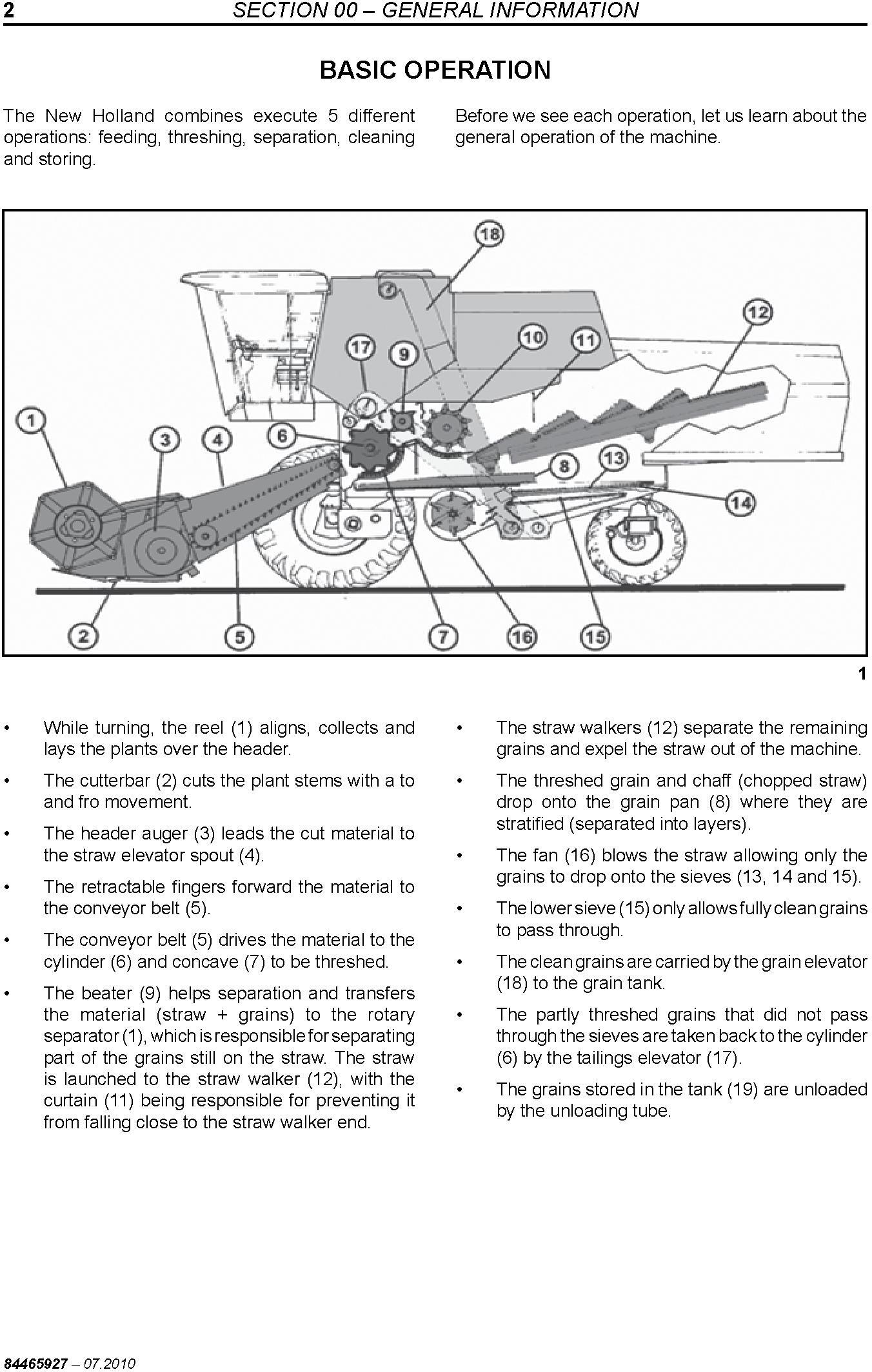
BASIC OPERATION
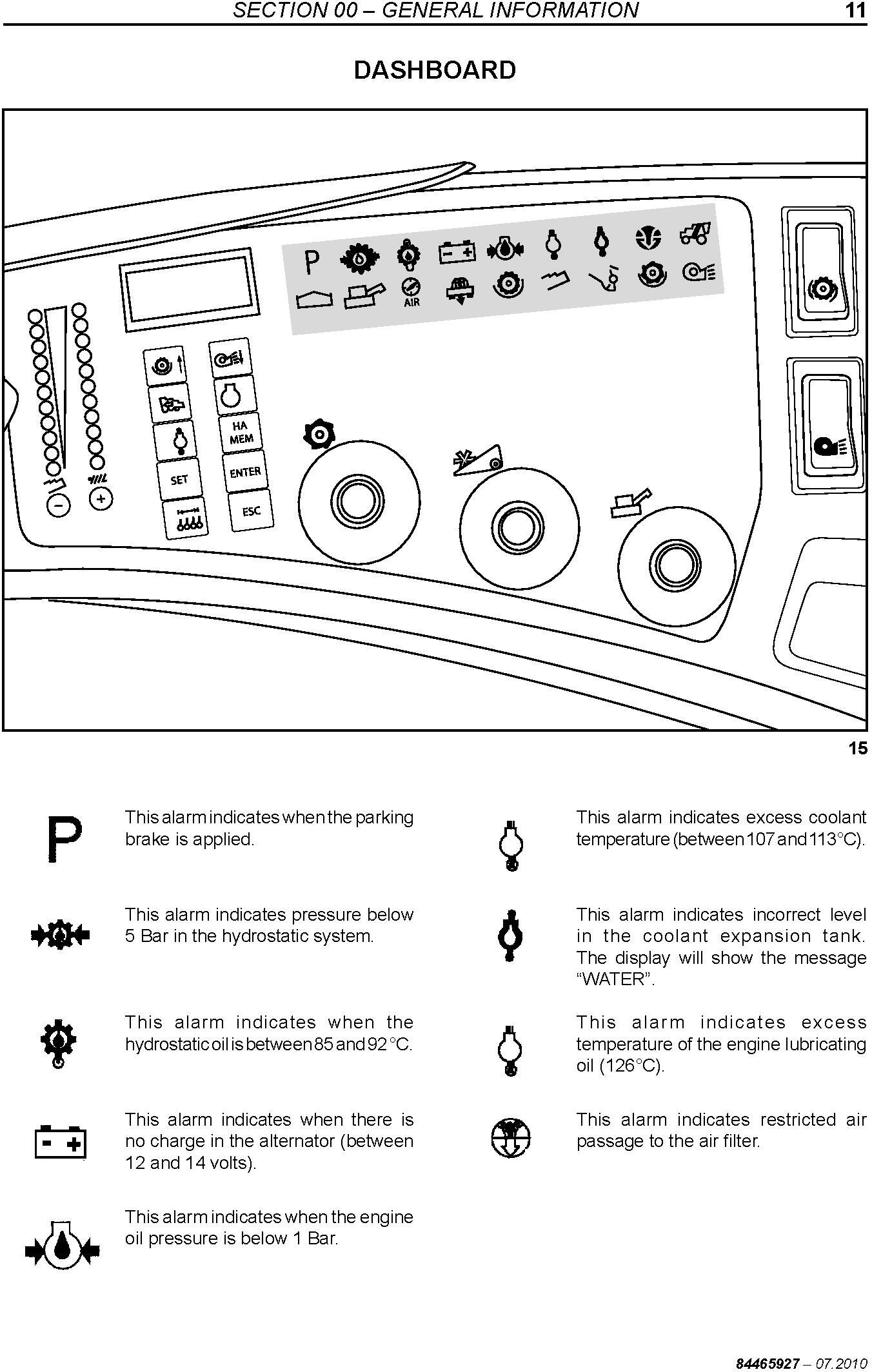
DASHBOARD
LOSS CONTROL (A)
General Module (B)
CALIBRATION KEYS
DISPLAY PROGRAMMING
DASHBOARD
DRIVE KEYS [hydrostatic transmission]
CONTROLS [hydrostatic transmission]
Multifunction Lever
DRIVE KEYS [mechanical transmission]
CONTROLS [mechanical transmission]
Chapter 3 - Maintenance
Lubricant specifications
MAINTENANCE AND LUBRICATION SCHEMATICS
ADJUSTMENTS AND MAINTENANCE
DRIVE BELTS AND CHAINS [right-hand side]
STEERING AXLE
AIR CONDITIONER
Chapter 4 - Field Adjustment
Safety Precautions for Operating on Hills
COMBINE ADJUSTMENTS
MEASURING GRAIN LOSS
LOSSES FROM THE MACHINE
troubleshooting
Section 10 - ENGINE
SPECIFICATIONS
ASSEMBLY DIMENSIONS
TIGHTENING TORQUES
Special tools
Engine Cold Starting
Cooling System
Lubrication System
Fault diagnosis
Installing the engine on the trestle
ENGINE DISASSEMBLY
Assembling the engine
checking and measuring
Valve clearance adjustment
ROTARY injection pump removal, installation and synchronization
Section 21 - TRANSMISSION
Gearbox 3MD
GEARBOX - TC5070 MECHANICAL
GEARBOX - TC5070 HYDRO
SPECIFICATIONS
Disassembly Sequence
Coupling and Inversion Carcass
Differential
Assembly Sequence
Section 22 - Drive clutch
DRIVE CLUTCH [mechanical transmission]
REAR WHEEL TOE-IN
Section 23 - Drive variator
Belt Tension Adjustment
Variator Adjustment
Variator Alignment
Section 25 - FRONT MECHANICAL TRANSMISSION
Chapter 1 - Standard Final Drive
STANDARD REDUCER ratio 10/75
WHEEL BOLT - REPLACEMENT
FINAL DRIVE - Removal/Installation
FINAL DRIVE - Disassembly/Assembly
Chapter 2 - Rice Final Drive
Specifications
Rice Drive Ratio 10/75
Section 33 - BRAKES
Chapter 1 - Brake Pad Replacement
BRAKE PAD REPLACEMENT
Chapter 2 - Brakes
BRAKES
Section 35 - hydraulic system
Chapter 1 - Basics
specifications
HYDRAULIC SCHEMATICS - TC5070 Mechanical
HYDRAULIC SCHEMATICS - TC5070 Hydro
HYDRAULIC SYSTEM
HYDRAULIC CONTROL - FULL SET
HYDRAULIC CYLINDERS
HYDROPNEUMATIC COMPENSATORS AND CYLINDERS
Chapter 2 - Hydraulic Motors
REVERSER HYDRAULIC MOTOR REMOVAL, INSTALLATION, DISASSEMBLY, INSPECTION AND ASSEMBLY
Practical maintenance tips for the HYDRAULIC MOTOR - PARKER
Chapter 3 - Steering
SPECIAL TOOLS
SPECIFICATIONS
STEERING VALVE
PUMP GROUP
Chapter 4 - Hydrosatic System
GENERAL PRINCIPALS
HYDROSTATIC TRANSMISSION
HYDROSTATIC SYSTEM (TC5070 Hydrostatic transmission)
Hydrostatic System mechanical adjsutments
HYDROSTATIC CIRCUIT AND COMPONENTS
MULTIFUNCTION VALVE
Disassembling and assembling the main components
Troubleshooting and measurement points
Chapter 5 - Auxiliary Drive I (4WD)
HYDROSTATIC CIRCUIT - AUXILIARY DRIVE
MAINTENANCE PROCEDURES
SHAFTS/GASKETS AND BEARINGS
Block and piston set
DISTRIBUTOR (VALVE BLOCK) AND DISTRIBUTION GASKETS
ACCUMULATOR
Chapter 6 - Auxiliary Drive II (4WD)
WHEEL MOTOR MAINTENANCE
Preventive Maintenance and Precautions
General Recommendations
TROUBLESHOOTING
Wheel Motors
WHEEL MOTOR OPERATION
General Information
Description
DISASSEMBLY AND ASSEMBLY OF THE REAR AXLE
Disassembly
Assembly
REAR AXLE MAINTENANCE
Basic maintenance requirements
Every 100 hours of Machine Operation:
Cross-section
Every 100 hours of Machine Operation:
STARTING PROCEDURE
TEST GAUGE LOCATIONS
Test Procedure Nº 2
Test Procedure Nº 3
TESTING PROCEDURE
Test Procedure Nº 1
Test Pressures versus Mode of Machine Operation
Troubleshooting
Fluidrive Rear Drive Systems
GENERAL INFORMATION
Safety Measures
Operation of the Fluidrive System
Chapter 7 - Troubleshooting
Troubleshooting the Hydraulic Circuit
Section 36 - Pneumatic System
Chapter 1 - Pneumatic System
SYMBOLS USED
HYDRAULIC CONTROL ROD ACTUATOR CYLINDER
MICRO SOLENOID VALVE 3/2 PORTS - NC (Normally Closed)
PNEUMATIC COMPONENTS
PNEUMATIC EQUIPMENT
PRESSURE REGULATOR
PNEUMATIC SYSTEM
PNEUMATIC SCHEMATIC
Chapter 2 - Pneumatic components
Pneumatic clutch
Section 48 ‒ TRACKS
Specifications
Assembly Torques
TRACKS
MAINTENANCE
TRACK INSTALLATION
TOWING INSTRUCTIONS FOR HARVESTERS EQUIPPED WITH TRACKS
Section 50 ‒ CLIMATE CONTROL/AIR CONDITIONER
Chapter 1 - A/C SYSTEM
Introduction
AIR CONDITIONING CIRCUIT
A/C CYCLE
COOLANT
TESTING AND TROUBLESHOOTING, GENERAL
PRELIMINARY TROUBLESHOOTING AND TESTING
PRELIMINARY DIAGNOSTICS CHART
TEST PROCEDURE ‒ STABILIZING THE SYSTEM TEST PORTS
A/C SYSTEM PERFORMANCE TEST AND DIAGNOSTICS CHART
GAUGE READINGS AND INTERPRETATIONS
Chapter 2 - CONDENSER
Description
Chapter 3 - FILTER DRIER
Description
Section 55 ‒ ELECTRICAL SYSTEM
Chapter 1 ‒ Specifications
SPECIFICATIONS
Chapter 2 ‒ Component Identification
SWITCHES
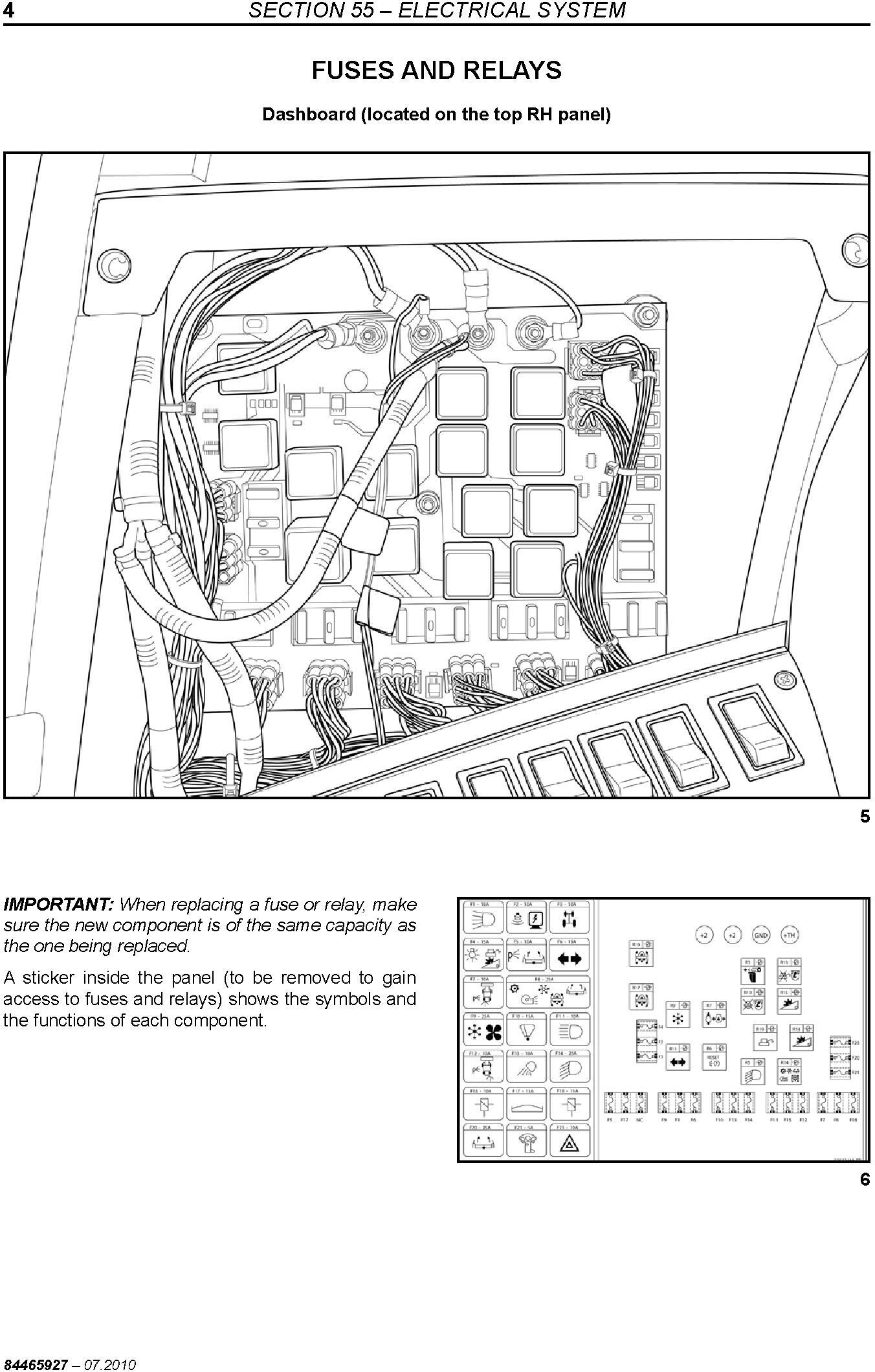
Fuses and relays
SUMMARY OF ALARMS
ALERT CONDITIONS
Chapter 4 ‒ Troubleshooting Diagram
TROUBLESHOOTING
Chapter 5 ‒ Electric Schematics
ELECTRICAL SYMBOLOGY
ELECTRICAL SCHEMATICS
Section 60 ‒ PRODUCT FEEDING
Straw Elevator
Stone Trap
STRAW ELEVATOR TRACK CHAINS
UPPER SHAFT
Check the dimensional
Section 66 ‒ THRESHING
Chapter 1 ‒ Cylinder and concave
THRESHING CYLINDER
CONCAVES
TEETH CONCAVE OPENING (RICE)
Section 72 ‒ Separation
Chapter 1 ‒ Beater
BEATER
Chapter 2 ‒ Rotary Separator
Rotary Separator
Chapter 3 ‒ Straw Walker
Straw Walker
Chapter 4 ‒ Grain pan
GRAIN PAN
Section 74 - CLEANING
Fan
CANVAS AIR DEFLECTOR
Replacement of the fan belts
VARIATOR ADJUSTMENT DEVICE
Fan Case
SIEVES
FITTING THE GRAIN PAN DIVIDERS
Section 80 ‒ GRAIN STORAGE
Grain and tailings auger
Leveling Auger and Tailings
Unloading tube auger
Section 88 ‒ ACCESSORIES
Chapter 1 ‒ Straw Chopper
STRAW CHOPPER
TROUBLESHOOTING
Section 90 ‒ HEADER, CAB, BODYWORK AND DECALS
Chapter 1 ‒ Coupling grain header and corn spout
CUTTING PLATFORM
C.A.A.P. Adjustment/F.3L.
BLADES AND BLADE BOX
REEL
FEED AUGER
Chapter 2 ‒ Cutter bar drive box
Disassembly
TROUBLESHOOTING
ADJUSTMENTS FOR THE CORN HARVEST
FIELD WORK
ADJUSTMENTS AND MAINTENANCE
LUBRICATING NIPPLES
Grease Nipples
Transmission Boxes
Chains
Chain maintenance after the harvest
SERVICE SCHEDULE
LUBRICATION
ROW UNIT SAFETY CLUTCH (TORQUE LIMITER)
DISASSEMBLY OF THE GEARBOX AND ROW UNIT SAFETY CLUTCH
Gearbox
Removal of the gearbox
Stalk rolls ‒ Synchronism of the pullers
Gearbox disassembly
Disassembly and assembly of the safety clutch
Reinstallation of the divider points and dividers
Retaining bracket
Ear saver
ROW UNIT TRANSMISSION BOX
ARTICULATED DIVIDER POINTS
Articulated Points
Drag Plates
Angle of Inclination of Row Units
Vertical Inclination of the Row Units
Row Unit Attachments
Row Unit Drive
SETTING THE DISTANCE BETWEEN ROWS
SETTING THE ROW UNITS
ROW UNIT GUARDS
REVERSER SYSTEM
DECK PLATES
LEFT SHIELD AND DEFLECTOR
ELECTRICAL CONTROL OF THE DECK PLATES
Corn Header Activation
Corn Header Height Control [mechanical transmission]
Corn Header Height Control [hydrostatic transmission]
Adjusting the Distance Between the Deck Plates
FEEDER AUGER AND ROW UNIT DRIVE
Feeder auger with total helix in the center
Feeder auger height
Adjustment of the safety clutch
FEEDER CHAINS
Stalk rolls
Replacement of the stalk rolls
Adjustment of the weed knives and the stalk rolls
Adjustments of the weed knives (Counter knives)
Stalk roll adjustment
PNEUMATIC SYSTEM
SIEVE
FAN
STONE TRAP
CONCAVE
STRAW ELEVATOR ADJUSTMENTS
Straw elevator chain tension
Adjustment of the front axle suspension spring
Chain
STRAW ELEVATOR ‒ HEADER COUPLING
Support Shoes
Coupling the corn header to the combine
HEADER SIZES
REQUIRED PROCEDURES FOR CORN
SPECIFICATIONS
INTRODUCTION
COMBINE CARE
END-OF-SEASON SERVICE
MAINTENANCE BETWEEN SEASONS
SERVICING BEFORE THE SEASON.
SAFETY NORMS
TOWING THE HARVESTER
TRANSPORTING THE MACHINE
Stopping the machine
Adjusting the machine
SPECIAL CARE
PRODUCT IDENTIFICATION
CONVERSION TABLE
TORQUE CHART
BASIC OPERATION
DASHBOARD
LOSS CONTROL (A)
General Module (B)
Instruments:
CALIBRATION KEYS
DISPLAY PROGRAMMING
DASHBOARD
DRIVE KEYS [hydrostatic transmission]
Function of switches
Complementary Switches and Controls
CONTROLS [hydrostatic transmission]
Multifunction Lever
DRIVE KEYS [mechanical transmission]
Function of switches
CONTROLS [mechanical transmission]
Safety Precautions for Operating on Hills
COMBINE ADJUSTMENTS
MEASURING GRAIN LOSS
Simplified Procedure
Specific Measurement Procedure
LOSSES FROM THE MACHINE
troubleshooting
Gearbox 3MD
GEARBOX ‒ TC5070 MECHANICAL
GEARBOX ‒ TC5070 HYDRO
SPECIFICATIONS
Technical data and adjustment values
Temperature for Assembly
Tightening Torques
Disassembly Sequence
Coupling and Inversion Carcass
Idler Shaft
Drive Shaft
Differential Cover
Differential
Differential
Gearbox Carcass
Assembly Sequence
Differential
Gearbox Carcass
Differential Cover
Drive Shaft
Idler Shaft
Reverse Shaft
Cover Adjustment
Fork assembly
Fork Setting
Adjusting the Variator Shaft Bearing Axial Clearance
Adjusting the idler shaft bearing axial clearance
Shift Cover
DRIVE CLUTCH [mechanical transmission]
Bleeding the clutch hydraulic command
REAR WHEEL TOE-IN
Rear axle pivot positions
Belt Tension Adjustment
Variator Adjustment
Variator Alignment
Specifications
Rice Drive Ratio 10/75
Disassembly
Assembly
BRAKE PAD REPLACEMENT
Removal
Installation
Brake shoe disasembly and assembly
BRAKES
SERVICE BRAKE ADJUSTMENT
PARKING BRAKE ADJUSTMENT
BLEEDING THE CONNECTION BETWEEN THE TWO MAIN CYLINDERS
BLEEDING THE RIGHT-HAND CIRCUIT
REVERSER HYDRAULIC MOTOR REMOVAL, INSTALLATION, DISASSEMBLY, INSPECTION AND ASSEMBLY
Preliminary Preparation for Disassembly
Removal and Installation
Disassembly and Inspection
Assembly
Final check
Rotor assembly
Practical maintenance tips for the HYDRAULIC MOTOR ‒ PARKER
SPECIAL TOOLS
SPECIFICATIONS
STEERING VALVE
Characteristics
Removal
Installation
Disassembly
Assembly
PUMP GROUP
Main hydraulic pump
Hydraulic pump (steering circuit)
Hydraulic pump (side floating circuit)
HYDROSTATIC CIRCUIT - AUXILIARY DRIVE
How it Works
MAINTENANCE PROCEDURES
Wheel - motor cut view
Wheel - motor component
SHAFTS/GASKETS AND BEARINGS
Disassembly
Assembly
Block and piston set
Disassembly
Assembly
DISTRIBUTOR (VALVE BLOCK) AND DISTRIBUTION GASKETS
Disassembly
Assembly
ACCUMULATOR
Description and operation
Disassembling the accumulator
Information to replace the accumulator
Installing the accumulator
GENERAL PRINCIPALS
Circuit
Description and operation of the variable yield pump
Description and operation of the hydrostatic motor
Operation of the fixed displacement motor
Rotating direction
HYDROSTATIC TRANSMISSION
Hydrostatic pump (cut view)
Hydrostatic motor (cut view)
HYDROSTATIC SYSTEM (TC5070 Hydrostatic transmission)
Technical Data
Hydrostatic system oil change and refilling
Hydrostatic System mechanical adjsutments
Adjust the control cable
Belt tension adjustment
HYDROSTATIC CIRCUIT AND COMPONENTS
MULTIFUNCTION VALVE
Disassembling and assembling the main components
Troubleshooting and measurement points
Hydrostatic pump
CHARGE PUMP
Disassembly
Assembly
Hydrostatic motor
GENERAL INFORMATION
Safety Measures
Operation of the Fluidrive System
Troubleshooting
Fluidrive Rear Drive Systems
TESTING PROCEDURE
Test Procedure Nº 1
Test Pressures versus Mode of Machine Operation
TEST GAUGE LOCATIONS
Test Procedure Nº 2
Test Procedure Nº 3
STARTING PROCEDURE
REAR AXLE MAINTENANCE
Basic maintenance requirements
DISASSEMBLY AND ASSEMBLY OF THE REAR AXLE
Disassembly
Assembly
WHEEL MOTOR OPERATION
General Information
TROUBLESHOOTING
Wheel Motors
WHEEL MOTOR MAINTENANCE
Preventive Maintenance and Precautions
Troubleshooting the Hydraulic Circuit
Steering
Header
Reel
Unloading Tube
Drive Variator
Lateral Flotation
Reverser
Others
SYMBOLS USED
HYDRAULIC CONTROL ROD ACTUATOR CYLINDER
Installation of the sintered filter
MICRO SOLENOID VALVE 3/2 PORTS - NC (Normally Closed)
PNEUMATIC COMPONENTS
Solenoid Valve
Rotary Joint
Drier Filter
Pneumatic Cylinder
Reverser Pneumatic Cylinder
Ball Valve
PNEUMATIC EQUIPMENT
Selector Valve ("OR" Element)
Ball Valve
Reverser Control Valve
PRESSURE REGULATOR
Schematic
Lubricator
PNEUMATIC SYSTEM
PNEUMATIC SCHEMATIC
Pneumatic clutch
Removing the pneumatic clutch
Disassembling the pneumatic clutch
Assembling the pneumatic clutch
Disassembling the pneumatic clutch
Assembling the pneumatic clutch
Specifications
Assembly Torques
TRACKS
New Holland Tracks for Rice Harvesters
Introduction
Front Axle
Rolling material
Straw elevator
Drive Wheels
Shoes
Attaching to the Harvester
Rear Tires
MAINTENANCE
TRACK INSTALLATION
TOWING INSTRUCTIONS FOR HARVESTERS EQUIPPED WITH TRACKS
Introduction
Correct use of the air-conditioning system
Storage maintenance
AIR CONDITIONING CIRCUIT
Location of the A/C components
A/C CYCLE
Air-conditioning process
Lubricants
Operation
COOLANT
Refrigerant recovery procedure
Washing
Recharge/Refilling
Use of a manifold gauge set
Checking refrigerant for excess air
Containers for the storage of recycled refrigerant
Transfer of refrigerant
Disposal of empty or near empty disposable containers
Applicable SAE standards
Related SAE standards
TESTING AND TROUBLESHOOTING, GENERAL
General safety and service precautions
Check for leaks
Cleanliness
Refilling
Contaminants
Prevent mixing of service equipment
PRELIMINARY TROUBLESHOOTING AND TESTING
Operational checks ‒ Heating
Operational checks ‒ A/C
PRELIMINARY DIAGNOSTICS CHART
TEST PROCEDURE ‒ STABILIZING THE SYSTEM TEST PORTS
A/C SYSTEM PERFORMANCE TEST AND DIAGNOSTICS CHART
GAUGE READINGS AND INTERPRETATIONS
Description
Removal
Installation
Description
Troubleshooting
Removal
Installation
SPECIFICATIONS
SWITCHES
Fuses and relays
SUMMARY OF ALARMS
ALERT CONDITIONS
Cylinder VARIATOR BELT ‒ Removal/Installation
THRESHING CYLINDER VARIATOR DRIVEN DISKS ‒ Removal/Installation
Threshing cylinder variator drive disks ‒ Removal/Installation
CYLINDER VARIATOR ADJUSTMENT
BEATER
Specifications
Replacement of the shaft and the bearings
Rotary Separator
Speed adjustments
Procedure to replace the Rotary Separator
Straw Walker
Fitting the crests
Position of the crests
Disassembly of the straw walker and shafts
Assembly of the straw walker shafts
Care during shaft installation
Straw walker bearings
GRAIN PAN
Characteristics
Disassembly and assembly of the grain pan and the stone trap
Fan
CANVAS AIR DEFLECTOR
Replacement of the fan belts
VARIATOR ADJUSTMENT DEVICE
Fan Case
Disassembly
Assembly
SIEVES
Types of sieve available
Factory sieve adjustment
Removing the sieves
Installation
Installation of the Upper Sieve with Self-Leveling System
FITTING THE GRAIN PAN DIVIDERS
Grain and tailings auger
Disassembly
Assembly
Leveling Auger and Tailings
Tensioning of the grain/tailings elevator conveyor chains
Disassembly of the leveling auger
Assembly
Disassembly of the tailings auger
Assembly of the tailings auger
Unloading tube auger
Disassembly of the unloading tube and auger
Installation of the unloading tube and auger
Adjustment of the unloading auger bearing
STRAW CHOPPER
SPECIFICATIONS
OPERATION
Deflector
Straw guide vanes
BELT TENSION ADJUSTMENT
Front belt
STRAW CHOPPER SPEED ADJUSTMENT
DEFLECTOR PLATE
TROUBLESHOOTING
CUTTING PLATFORM
Specifications
Cutting platform coupling to the harvester
Uncoupling the cutting platform
Horizontal leveling of the platform
Cutting platform
C.A.A.P. Adjustment/F.3L.
CAAP Adjustment
Lateral Flotation Adjustment
BLADES AND BLADE BOX
Maintenance of the blade drive box
Knife Replacement
Cutter Bar Alignment
Blade Adjustment
REEL
Leveling
Vertical adjustment
Hydraulic Horizontal Adjustment
Positioning of fingers
Tensioning the drive chain
FEED AUGER
Drive
Specifications
Flotation adjustment of the auger/retracting fingers
Disassembly
Assembly
SPECIFICATIONS
HEADER SIZES
STRAW ELEVATOR ‒ HEADER COUPLING
Support Shoes
STRAW ELEVATOR ADJUSTMENTS
CONCAVE
STONE TRAP
FAN
SIEVE
PNEUMATIC SYSTEM
FEEDER CHAINS
Stalk rolls
Replacement of the stalk rolls
Adjustment of the weed knives and the stalk rolls
FEEDER AUGER AND ROW UNIT DRIVE
Feeder auger with total helix in the center
Feeder auger height
Adjustment of the safety clutch
ELECTRICAL CONTROL OF THE DECK PLATES
Corn Header Activation
Corn Header Height Control [mechanical transmission]
Corn Header Height Control [hydrostatic transmission]
Adjusting the Distance Between the Deck Plates
REVERSER SYSTEM
DECK PLATES
LEFT SHIELD AND DEFLECTOR
SETTING THE DISTANCE BETWEEN ROWS
ARTICULATED DIVIDER POINTS
ROW UNIT TRANSMISSION BOX
ROW UNIT SAFETY CLUTCH (TORQUE LIMITER)
DISASSEMBLY OF THE GEARBOX AND ROW UNIT SAFETY CLUTCH
LUBRICATION
SERVICE SCHEDULE
LUBRICATING NIPPLES
Grease Nipples
Transmission Boxes
Chains
ADJUSTMENTS AND MAINTENANCE
FIELD WORK
ADJUSTMENTS FOR THE CORN HARVEST
TROUBLESHOOTING

