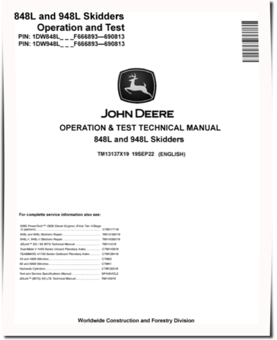
John Deere 848L and 948L (SN. F666893—690813) Grapple Skidders Operation and Test Manual (TM13137X19)
Specifications
-
Type Of DocumentOperation and Test Manual
-
Emission StandardsFinal Tier 4, Stage IV
-
Type of equipmentGrapple Skidder
-
Model848L, 948L
-
Serial Number666893-690813
-
PIN1DW848L_ _ _ F666893-690813, 1DW948L_ _ _ F666893-690813
Details
Table of Contents:
Introduction
Foreword
Manual Identification - READ THIS FIRST!
General Information
Safety
Diagnostics
Engine Control Unit (ECU) Diagnostic Trouble Codes
Hydraulic Valve Controller (HVC) Diagnostic Trouble Codes
Left Joystick Controller (JSL) Diagnostic Trouble Codes
Right Joystick Controller (JSR) Diagnostic Trouble Codes
Operator Interface Controller (OIC) Diagnostic Trouble Codes
Switch Module 1 (SM1) Diagnostic Trouble Codes
Transmission Control Unit (TCU) Diagnostic Trouble Codes
Cab Control Unit (CAB) Diagnostic Trouble Codes
Propulsion and Steering Controller (PSC) Diagnostic Trouble Codes
Reel Motor Controller (RMC) Diagnostic Trouble Codes
Vehicle Control Unit (VCU) Diagnostic Trouble Codes
Valve Power Control (VPC) Diagnostic Trouble Codes
Cab Switch Module (CSM) Diagnostic Trouble Codes
CAN Gateway Controller 1 (CGC) Diagnostic Trouble Codes
CAN Gateway Controller 2 (RCU) Diagnostic Trouble Codes
Operational Checkout Procedure
Operational Checkout Procedure
Engine
Theory of Operation
System Diagrams
Diagnostic Information
Adjustments
Tests
Electrical System
Theory of Operation
System Diagrams
Diagnostic Information
Monitor Operation
Diagnostic Test Box
Adjustments
Tests
Power Train
Theory of Operation
System Diagrams
Diagnostic Information
Adjustments
Tests
Hydraulic System
Theory of Operation
System Diagrams
Diagnostic Information
Adjustments
Tests
Winch
Theory of Operation
System Diagrams
Diagnostic Information
Tests
Heating and Air Conditioning
Theory of Operation
System Diagrams
Diagnostic Information
Tests
APPENDIX
Section 9000
Section 9001
Section 9005
Section 9010
Section 9015
Section 9020
Section 9025
Section 9030
Section 9031


